
Lab Goal
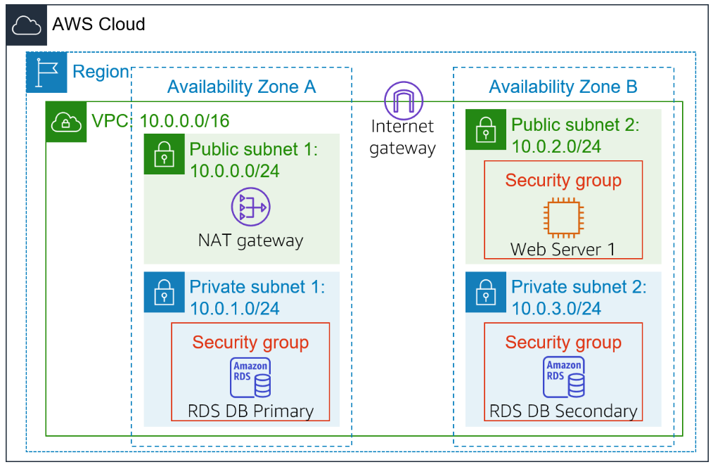
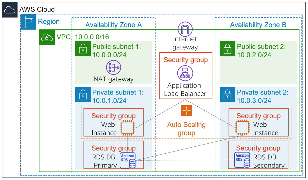
In this lab, we aim to create an infrastructure integrated with auto scaling and load balancing. We will try to deploy an application load balancer in this scheme. We start with an infrastructure shown in figure 1 and aim to create the infrastructure pictured in figure 2.
Create an AMI for Auto Scaling
Creating the AMI will enable us to create an instance can be deployed with identical content. This AMI will be used by the Auto scaling group. To start, go to EC2 dashboard and look through Instances. You shoud be able to see Web Server 1.
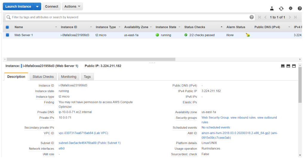
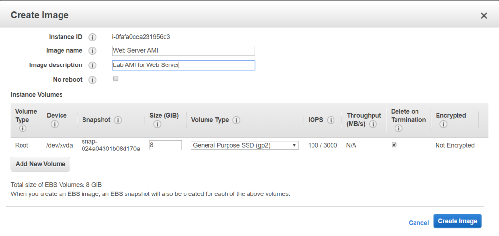
Before making any actions, make sure the status checks shows 2/2 checks passed. Continue with the AMI creation by going to Actions > Image > Create Image. Configure the name and description as below. We will use the volumes which is attached to the current instance then click Create Image.
Create a Load Balancer
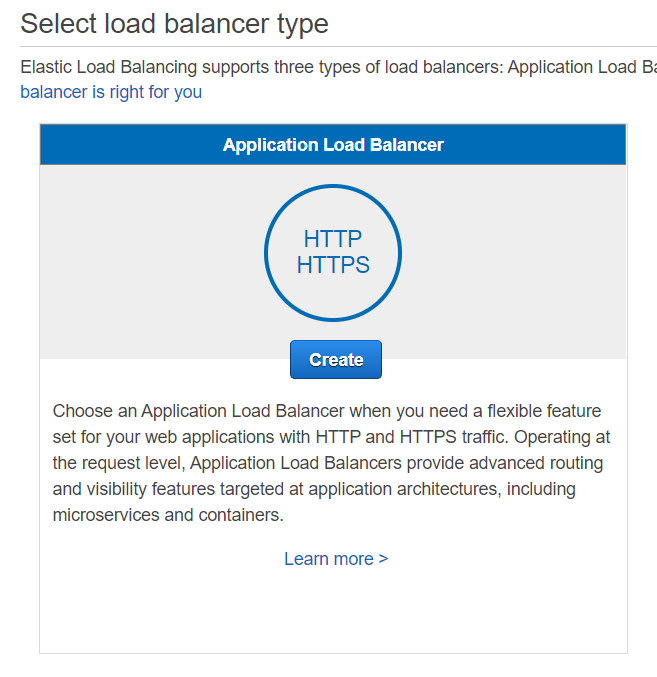
Go to Load Balancer from the left pane, then click on Create Load Balancer. In the first page, choose the Application Load Balancer.
In the Configure Load Balancer page, give the load balancer a name. Configure the Availability zone as below. Go to the next page and ignore any warning for now.

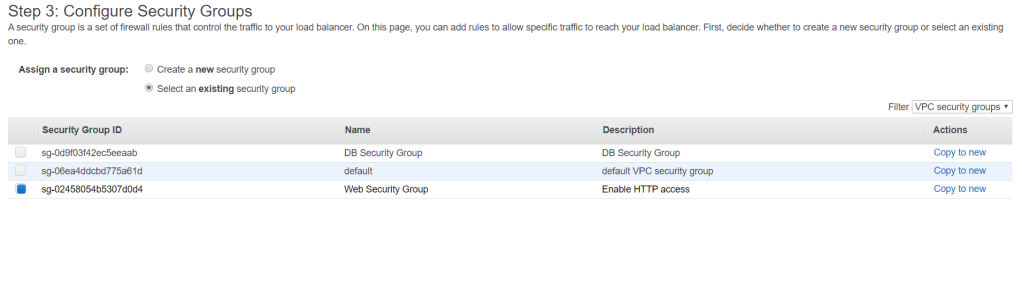
In the Security Group Configuration page, select the Web Security Group and deselect the defualt one. Go to the next configuration.
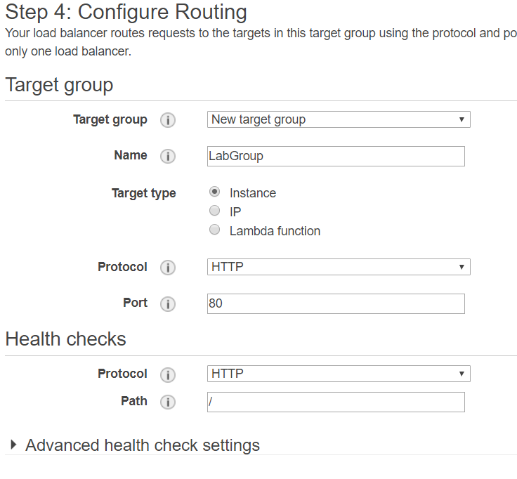
Create a new target group and give it a name. Leave the rest as default and click Next.
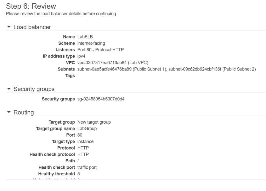
Leave the Register Target as it is. Auto Scaling will be the one which registers the instances. Click Next to review. Then click Create.
Create Launch Configuration and Auto Scaling Group
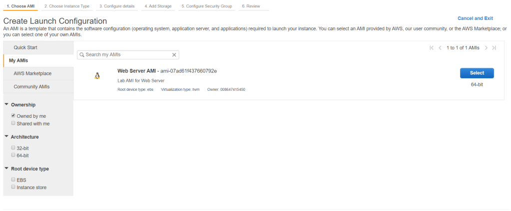
From the left pane, go to Launch Configuration and click Create launch configuration. Select MyAMI from the left pane and the previous AMI we created is there. Select the image.
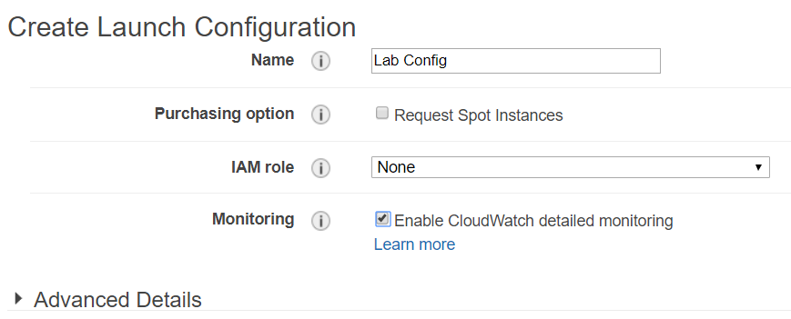
Select the t2.micro on the instance type selection. Configure the launch configuration details as below. Click Next.
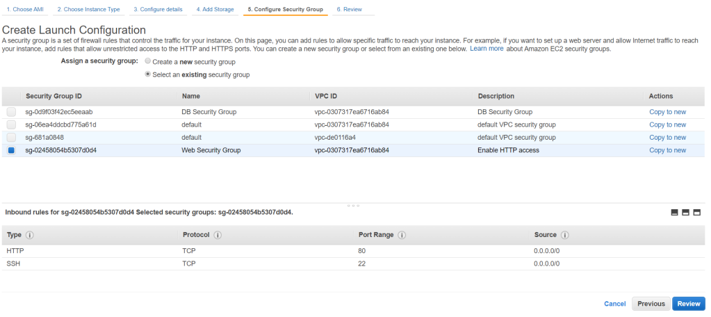
We will use the default storage for this purpose and click Next. For the security group, select an existing one which is the Web Security Group. Click Review and then finish by clicking Create launch configuration.
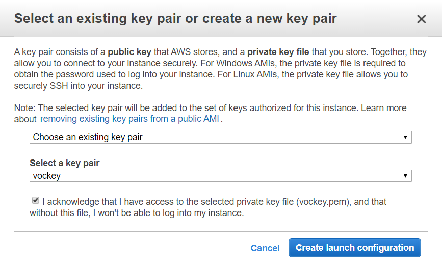
You will need also need to specify a key pair. Select an existing one and check the check box then click Create launch configuration.
The completion page will appear and you can find the Create an Auto scaling group using this launch configuration button. Click on it.
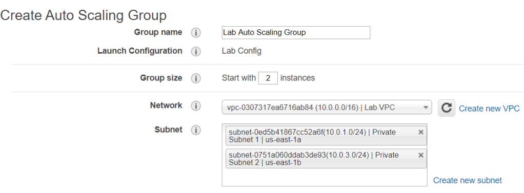
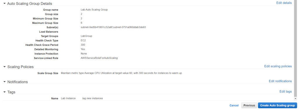
Configure the Auto Scaling Group details as below.
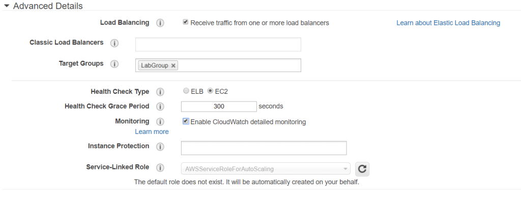
Expand Advanced details and configure as below.
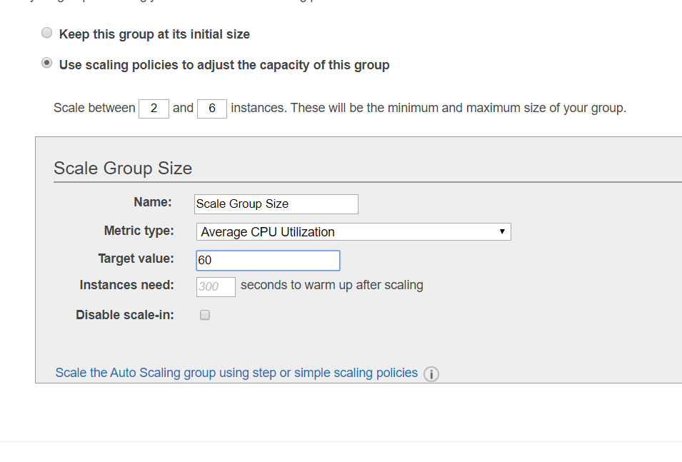
Next, configure the scaling policies as below. Target value indicates the average CPU utilization percentage of each instance. Auto Scaling will increase or decrease instances to meet the target value. Click Next.
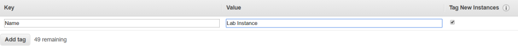
We would not need any notification for this lab. Click next to the tags page. Add the tag as below. The tags will also apply for the instances created. Click review.
Review the Auto Scaling group configurations and then click Create Auto Scaling group to initialize. If you receive a failed message, retry the failed task and it should be successful.
Verify Load Balancing is Working
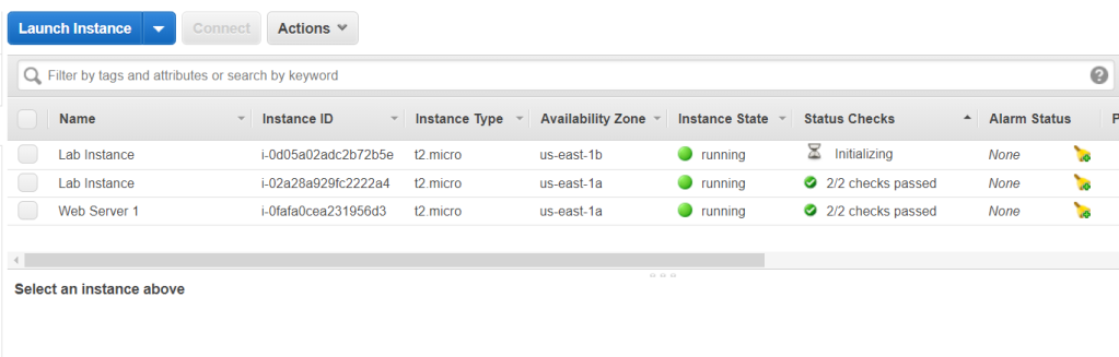
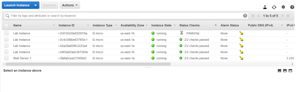
From the EC2 dashboard, select Instances from the left pane. There are now 3 instances in which 2 of them created by the auto scaling group.
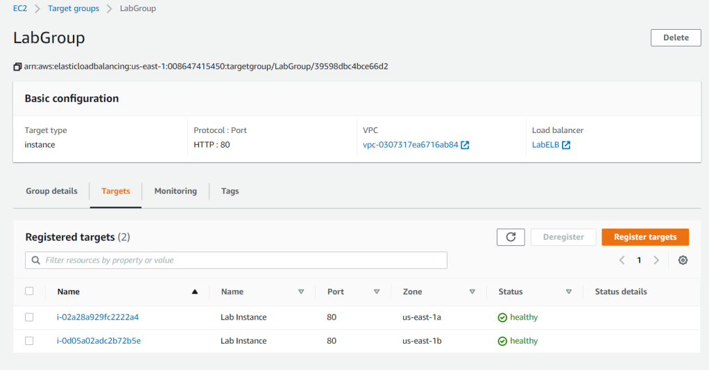
Go to Target Groups from the left pane and click the LabGroup then go to Targets tab. Make sure both instances status indicate healthy.
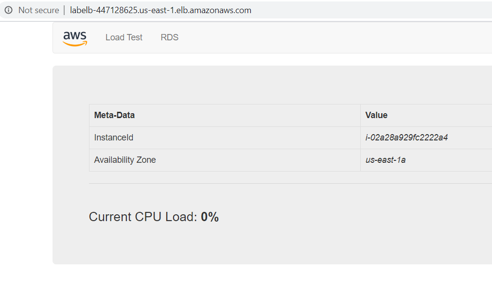
Move to the Load Balancer page from the left pane. Under the Description tab, copy the DNS and open it up in a browser. You will recieve the application from the EC2 as the Load Balancer sent the request to it which indicates that it is working. Do not close the applicationa s we will use it for the next task.
Test Auto Scaling
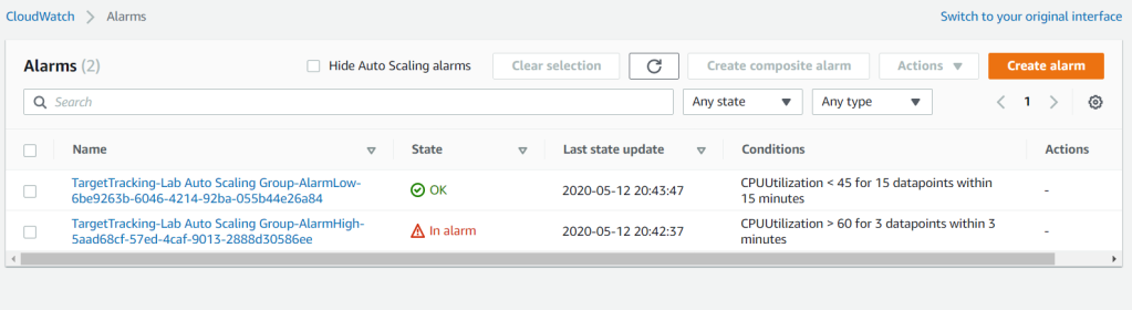
Go to CloudWatch from Services and select Alarms from the left pane. There should be 2 alarms which were created by Auto Scaling group to maintain the utilization at 60% and the instance between 2 to 6.

Click the top alarm with the OK state (OK means the alarm is not trigerred). In this page, we will see how the application CPU utilizations behave.
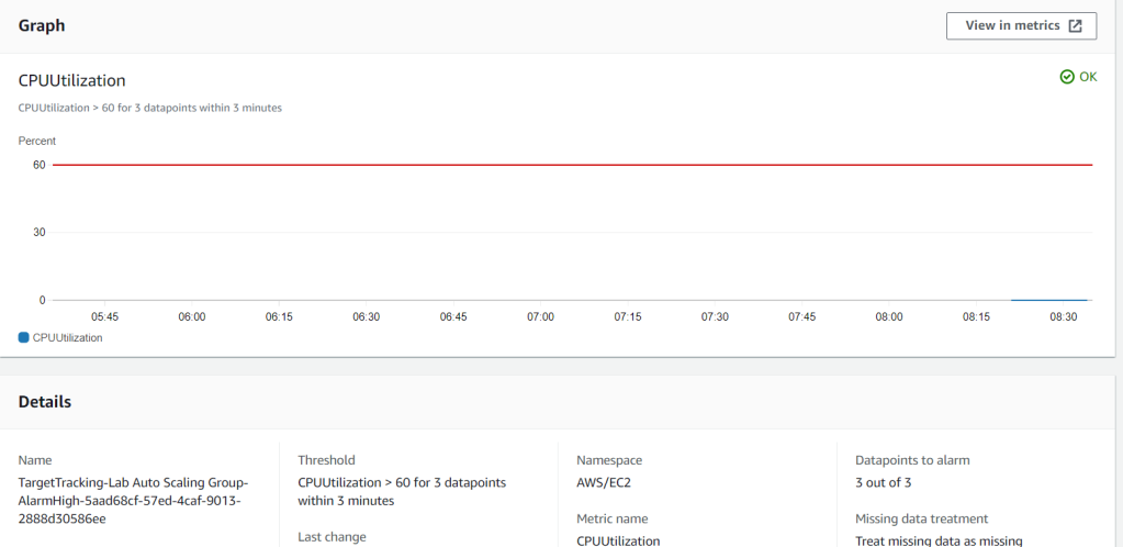
Go back to the application and select teh Load Test page to generate a high CPU load. Wait until around after 3 minutes and the AlarmHigh will be in In alarm state which means trigerred and the AlarmLow is in the OK state.
Going back to EC2 instances, you will see that there will be an increased number of instances from Auto Scaling.
Delete the Web Server 1 instance as it is no longer needed.
Critical Thinking
Just as implementing it in EC2, Auto Scaling can also be used to control DynamoDB tables to increase or decrease its read and write capacity. Target utilization provides the same concept as the one we implemented in this lab. It is the percentage of consumed provisioned throughput. It can measure the traffic and the number will become a reference for the Auto Scaling group to manage the instance whether it should be scaled or not. This concept is also combined with CloudWatch alarms to trigger the scaling actions.
However, Elastic Load Balancer (ELB) serves a different purpose in this lab. As stated before, we used the application load balancer which specifically purposed to distribute traffic through EC2 instances. Elastic load balancer is capable to distribute incoming application traffic throughout different instances in different availability zones. ELB works with a listener which keeps in contact with the attached instances. The listener will help ensure the health of the instances in the target group is working fine. If there is something wrong with one of the routing, ELB will automatically redirects the traffic to the healthy target groups.
Another ELB which we did not cover in the lab is the network load balancer. While application load balancer distributes HTTP and HTTPS traffic, network load balancer distributes TCP traffic. The set up is similar to an application load balancers with listeners and target groups for distributions. You can distribute network load balancer in each availability zone which will be assigned its own static IP address. Through that points distributed in each availability zone, traffic will be distributed to the instances in its VPC subnets. Existing elastic IP addresses can also be implemented in each availability zones to gain better control on the network such as adding custom firewalls.
